When photographing deep sky objects, most motorized mounts can follow the photographed object for 30 seconds without the need for telescope guidance. During this period the stars will remain very round. Exceeding this period, the stars may be stretched or spun due to the imprecision of the frame's tracking. To increase the exposure time per photo, we must have recourse to the manual guidance or the autoguiding of the telescope.
Manual guidance of the telescope consists of following visually, with a unlimited reticulated eyepiece, a guide star and to make the guide corrections manually via the control lever of the motorized mount. Throughout the period of exposure of the deep sky object photo, the operator must continuously look through the eyepiece and make corrections manually. If the total exposure time (including the images by compositing) is two hours or more (today, several astrographers expose more than one night!), We can see that this operation is very exhausting and requires operator foolproof dexterity! We can thus consider that this solution is completely outdated with exposure times of 2 hours and more.
The telescope's autoguiding consists in automating the guidance of the mount via a small camera (guidance, planetary, CCD, CMOS, etc.) or a webcam. Autoguiding is therefore preferable to manual guidance because, once started, everything is automated. The operator can go to relax or go about other tasks during the whole guidance period.
Despite its simple operation, the following discussion describes all the difficulties to be solved in order to achieve quality autoguiding with exposure times of 10 minutes or more per photo. I know that many astrophotographers have difficulty achieving quality autoguiding with these exposure times. Often they are limited to a maximum of 2 to 5 minutes per photo. After this time, the stars appear to lengthen. Also, for the beginner in autoguiding, the solutions presented can seem complex to set up. But you have to go through your personal learning. I therefore invite all those who have difficulties in their autoguiding to read and understand the following presentation. You will then be able to resolve these difficulties and thus achieve autoguiding with exposure times of 10 minutes or more per photo. For the beginner, reading this presentation will save a lot of time in the search for quality autoguiding.
The operation of the autoguiding:
- Follow a guide star at exposure intervals of 1 to 4 seconds (recommended)
- If the guide star changes position or moves, the guidance software sends commands to the mount to re-center the star
There are two main autoguiding configurations:
- The optical divider (Off-Axis)
- The guide telescope mounted in parallel
The optical divide (Off-Axis)
Here is the material required for autoguiding with an optical splitter:
- An optical divider
- A second camera or webcam dedicated to autoguiding
- Software for autoguiding
- A motorized mount allowing movement control by autoguiding
- The cabling to connect the guide camera and the mount to the computer
- If necessary, the GPUSB module (see details towards the end of this talk)
Here is an example of an optical splitter (click on the image to enlarge):

The material presented above is that of the author. The optical divider is the Orion Thin Off-Axis Guide which, by its thickness of only 10,5 mm, allows its use on my Celestron Edge HD 800 telescope and my Orion 80ED telescope. The guide camera is a monochrome 120MM (ZWO) UPS which is very sensitive to light. Note that the optical splitter is installed in front of the filter wheel, thus providing maximum light transmission to the guide camera. Since I have been using this optical divider with the ASI 120MM camera, I have almost always found a guide star, even in my major light pollution site (Longueuil, in the suburbs of Montreal)!
Here is a view of the prism which returns a portion of the image to the ASI 120MM guide camera:

This consists of installing a guide camera between the imaging camera and the telescope, as shown. A small portion of the image is directed to the guiding camera via the optical splitter prism. The guidance will be excellent, even if you are not precisely aligned with the PôCelestial North (PNC), because the guiding camera is in the same field of view as the imaging camera. In addition, this solution eliminates the problems of bending (in English differential flexure) and drift caused by a guide telescope in parallel (see below). These are the two major advantages of this solution. But there are the following difficulties:
- Since there is just a small portion of the image which is directed towards the guide camera, then it is more difficult to find a guide star due to the restricted field of view offered by the optical splitter. We will then favor a guiding camera more sensitive to light to help us in this task.
- If a focal length reducer is used, which requires a precise distance, to the nearest mm, between the camera matrix and the reducer, the introduction of the optical divider risks extending this distance. There will then be the introduction of coma at the periphery of the image.
- For some Newton-type scopes and telescopes that have a short focusing length (MAP), the introduction of the optical splitter lengthens the distance between the telescope and the imaging camera. MAP then risks being impossible to achieve.
It should also be considered that the quality of the guide star which passes through the prism of the optical divider is lower than that offered by parallel guiding. Here is an illustrated example:
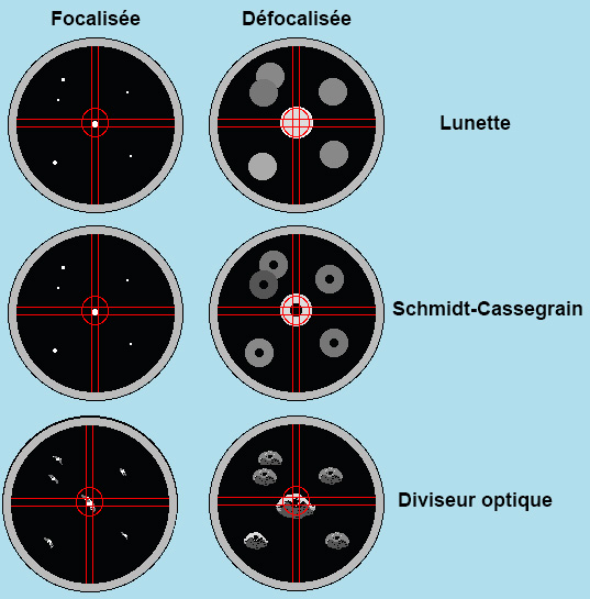
The first two images from the top illustrate the very good quality of guide stars offered by a parallel mounting of the guiding system using a telescope or a Schmidt-Cassegrain type optical tube. The third image provides an example of guide stars passing through the optical divider prism. They appear to distort for different reasons, the two main ones being:
- The guide star is located at the periphery of the field of view of the optical instrument. This one may have a coma problem (stars stretched out at the edges of the image). To alleviate this problem or make it disappear, it is necessary to use a coma corrector.
- The prism itself, which returns the image at a 45 degree angle, creates reflections and diffraction problems on the stars.
The quality of guide stars that pass through the optical divider varies from device to device, but there is always some distortion on the stars. In extreme cases, this can prevent quality autoguiding.
Considering the difficulties of this solution, one can understand that it will not always be possible to use it. Personally, I have chosen this solution. If I am unable to find a guide star, then I transfer my guide camera to my guide telescope, which represents my plan B.
It should also be considered that it is this solution which was, most of the time, adopted for manual guidance. Instead of using a guide camera, we used a illuminated reticulated eyepiece to follow the guide star by manually making corrections from the mount control lever.
The guide telescope mounted in parallel
Here is the equipment required for autoguiding in parallel:
- A second camera or webcam dedicated to autoguiding
- A telescope or telescope mounted in parallel with the main telescope
- A parallel mounting bracket such as a dovetail plate
- Tube rings allowing the telescope to be adjusted in focal length with the main telescope
- Software for autoguiding
- A motorized mount allowing movement control by autoguiding
- The cabling to connect the guide camera and the mount to the computer
- If necessary, the GPUSB module (see details towards the end of this talk)
Here is an example of assembly for autoguiding (click on the image to enlarge):

The material presented above is that of the author. For more details click on this lien.
For successful autoguiding in parallel, it is imperative to have a very precise alignment with the Celestial North Pole (PNC). This is the main difficulty of this solution. Also, we must consider the following difficulties:
- It is necessary to ensure the rigidity of the parallel assembly in order to avoid the problems of bending (differential flexure) between the imager and the guide telescope.
- The primary mirror of Schmidt Cassegrain telescopes which moves causing bending between the guide telescope and the imager. Prefer a telescope which allows the mirror to be blocked.
With the autoguiding in parallel, it is very easy to find a guide star, as the field of view is much larger than that offered by the optical splitter. In addition, you can choose a guide scope open to f / 5, for example, which will easily find a guide star in any circumstance. As the guide telescope is independent of the optical system of the imager, this solution adapts to all possible configurations of the imager. It is for these reasons that many astrographers choose this autoguiding solution.
But the main difficulty is the very precise alignment with the celestial North Pole:
- The mount must be perfectly level.
- The base of the frame must rest on a rigid ground so as not to lose the level of the frame (without this, there will be bending during the taking of photos).
- The guide telescope must have the same field of view as the imager (aim at the same place in the sky)
- In my experience, the polar alignment on the PNC should have an accuracy of 1 ′ of arc and less to allow exposure times per photo of up to 10 minutes. For exposure times per photo of more than 10 minutes, it is preferable to use an optical splitter (see above).
This precision is illustrated by the following graph:

The graph shows the drift caused by imprecise polar alignment. The cabin crew is not in line with the frame. The radius of the guide scope, which is mounted in parallel on the main telescope, is larger than that of the imager, as shown. Point A represents the start of the imaging session while point B represents the end. On the ray of the guide telescope, we see the tracking of the object from point A to point B. Look at what is happening on the ray of the imager with the two red circles. The difference is not the same between point A and B. This difference explains the constant drift of stars on the imager (which will produce elongated stars). Although the guide star remains well centered on the guide screen, there is constant drift on the imager because the imager's viewing radius is not the same as that of the guide scope. Here is the importance of a precise setting on the cabin crew.
Look at the graph again. If the PNC is in the axis of the mount, there is no more drift on the imager.
It should also be noted that if a guide telescope is used next to the main telescope (not on the top), the same precision on the PNC must be respected.
Also, the fact of having transferred my guide camera to theOrion mini guide, this made it possible to bring the radius of the guide telescope closer to that of the imager, thus minimizing the remaining drift.
The focal length of the guide telescope
I have seen all kinds of theory on the Internet about the length of the guide scope versus that of the imager. But, the bottom line is that most current autoguiding software allows autoguiding at a fraction of a pixel. So the only important point is to adjust the guiding camera sampling (in fraction of pixel) with the air turbulence. For example, air turbulence in Quebec is between 2 ″ of arc and 3,5 ″ of arc on average. The guiding camera sampling is adjusted to 1 ″ of arc (equal to a resolving power of 2 ″ of arc) which will allow autoguiding corrections to be made from 2 ″ of arc. Choosing a sampling of less than 1 ″ of an arc (in fraction of a pixel) is completely useless, because we will autoguide in the air turbulence, which risks sending too many contradictory corrections to the mount and thus creating errors of guidance.
To illustrate this, here is an example:
Using the guide scope Orion mini guide and the camera UPS 120MM (ZWO). By doing the calculations to know the sampling of the camera, we get 4,75 ″ of arc. To reduce the sampling to 1 ″ of arc, we use the fraction 0,21 (1 / 4,75 = 0,21). In PHD Guiding, we will enter in the field Minimum motion (pixels) : 0,21. We will then self-guide from 2 ″ of arc, ie above the air turbulence in very good observation conditions.
It is also suggested not to exceed 5 ″ of arc too much as sampling for the guide camera because in my experience I did not have maximized autoguiding with my old camera. DSI climb on theOrion mini guide. Sampling was 12,15 ″ of arc. The tracking quality was then increased to +/- 4 ″ of arc (8 ″ of arc in total) instead of +/- 2,5 ″ of arc (5 ″ of arc in total) which represents the performance of my mount CGEM self-guided in the sky of Quebec. By changing my autoguiding camera DSI (12,15 ″ arc sampling) for theASI (4,75 ″ arc sampling), I found this precision.
For full details on guiding camera sampling calculation, go to Astronomical calculations and go to the section The sampling of a pixel in arc second. You will then be able to perform your own calculations to establish the sampling of your guiding camera at 1 ″ of arc in fraction of pixel.
Autoguiding software:
Astronomical image acquisition software is supplied with most deep sky or planetary cameras. These softwares often offer autoguiding functions. Make sure that the software offers the operation drivers for the mount you have (if your mount offers compatibility with universal drivers). ASCOM, this will facilitate compatibility). Each software provides user manual for autoguiding.
There are also guidance cameras that allow self-guidance without connecting the camera to a computer. The camera has an autoguider port and the camera screen is used to configure autoguider and choose which star will be used to autoguide the mount. In this configuration, no computer is required. Personally, I do not recommend this solution to you, because I know people who had a lot of difficulty putting this solution in place. In addition, these cameras are limited in the autoguiding configuration parameters. Among other things, they do not allow fractional pixel autoguiding.
If you don't have autoguiding software with your camera (for example, you are using a webcam for autoguiding), here is some great free autoguiding software: PHD Guiding
Personally, I use PHD Guiding. It works great with my equipment and I recommend it to you.
Connect the mount to the computer for autoguiding
There are two ways to connect the mount to the computer to enable autoguiding:
- Via the joystick of the mount
- Using the mount's autoguider port (ST-4 compatible port)
Via the joystick of the mount
Most computerized mounts Goto provide autoguiding by connecting the computer to the mount's control stick via an RS232 cable. To achieve this link, with current computers, you have to buy an RS232 port and cable available at most computer stores. We connect everything to a USB port on the computer.
Using the mount's autoguider port
The best way to autoguide the mount is to use the autoguider port on the mount. So, if your mount has an autoguiding port, use this link. There are two ways to autoguide from the mount autoguider port:
- Using a guiding camera which is provided with an autoguiding port
- Using the module GPUSB
Using a guide camera
The autoguiding port of the mount is connected to the autoguiding port of the camera by using the cable provided by the guiding camera manufacturer or by purchasing a cable according to the manufacturer's specifications. The camera is connected to the computer via a USB cable (most of the time). Often, the manufacturer provides autoguiding software with the camera as well as instructions for use.
Using the module GPUSB
If you use, for autoguiding, a webcam or a camera not equipped with an autoguiding port, it is possible to autoguide by the autoguiding port of the mount using the module GPUSB. The module connects to a USB port on the computer and uses an RJ-12 cable (offered by the module manufacturer GPUSB) to connect the module to the autoguiding port of the mount (ST-4 compatible).
Personally I use this solution using software PHD Guiding and the camera UPS 120MM. The software is compatible with the module GPUSP and the camera UPS 120MM. The software connects to the camera UPS 120MM to self-guide on a star and on the module GPUSB to send guidance commands to the mount.
Richard Beauregard
Sky Astro - CCD
Revised 2021/10/28